
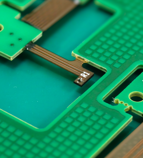
Modern electronic products continue to become smaller, lighter, and more sophisticated. From medical devices and automotive systems to aerospace equipment and consumer electronics, manufacturers need circuit solutions that provide reliable electrical connections while using available space efficiently. Rigid-flex printed circuit boards have become an important option for these applications because they combine the structural stability of rigid PCBs with the flexibility of flexible circuits.
Working with an experienced rigid flex pcb manufacturer can help businesses develop circuit boards that meet specific electrical, mechanical, and dimensional requirements. Rigid-flex technology can reduce the need for separate cables and connectors, simplify product assembly, and support compact electronic designs.
FastTurn PCBA provides PCB manufacturing and assembly solutions for businesses developing advanced electronic products. Understanding rigid-flex PCB construction, manufacturing processes, design considerations, and applications can help engineers select the right circuit technology for their projects.
What Is a Rigid-Flex PCB?
A rigid-flex PCB combines rigid circuit board sections with flexible circuit sections within a single integrated structure. The rigid areas provide stable surfaces for mounting electronic components, while the flexible sections connect different parts of the assembly and allow the board to bend or fold.
Traditional electronic products often use multiple rigid circuit boards connected through cables, wires, or separate connectors. Although this approach works for many applications, it can increase assembly complexity and occupy valuable space.
Rigid-flex technology offers an alternative by integrating rigid and flexible sections into one circuit assembly.
Key characteristics of rigid-flex PCBs include:
- Rigid sections for supporting electronic components.
- Flexible sections for connecting separate circuit areas.
- Reduced dependence on conventional wiring harnesses.
- Compact designs for space-constrained products.
- Custom board shapes and folding configurations.
- Potential reductions in assembly complexity.
- Integrated electrical connections between different product sections.
The exact construction depends on the application’s electrical requirements, mechanical constraints, layer count, and manufacturing specifications.
Why Choose FastTurn PCBA for Rigid-Flex PCB Manufacturing?
Selecting the right manufacturing partner is an important step when developing advanced electronic circuits. Rigid-flex PCBs require careful coordination between rigid board fabrication, flexible circuit processing, material selection, and final assembly.
FastTurn PCBA provides rigid flex pcb manufacturer and assembly solutions for various electronic development requirements. Businesses considering a rigid-flex project should communicate their technical specifications and confirm the manufacturer’s capabilities for the required construction.
Custom Manufacturing Solutions
Every electronic product has different requirements for dimensions, component placement, electrical performance, and mechanical movement.
A custom rigid-flex design may require specific layer configurations, controlled impedance, specialized materials, or carefully defined bend regions.
Before manufacturing begins, engineers should establish the required board dimensions, rigid-section thickness, flexible-section construction, copper weight, and electrical characteristics.
Clear specifications help manufacturers assess the design and identify potential production challenges.
Support for Complex Circuit Designs
Advanced electronic applications may require several circuit layers, dense routing, specialized connectors, and compact component arrangements.
Rigid-flex technology can support these requirements when the design is properly planned.
Engineers must consider the relationship between rigid and flexible sections to ensure that the final board meets its electrical and mechanical objectives.
Integrated PCB Assembly Considerations
Rigid-flex circuit boards may reduce the number of separate components needed to connect different circuit sections.
However, assembly requirements must be considered from the beginning of the design process.
Component placement, soldering requirements, connector access, and mechanical support can all influence the manufacturing approach.
Businesses should confirm that their selected manufacturer can support the required fabrication and assembly processes.
Major Benefits of Rigid-Flex PCB Technology
Rigid-flex PCBs offer several advantages for products that require compact construction, dependable electrical connections, and customized mechanical layouts.
1. Space-Saving Design
Rigid-flex circuits can fold into three-dimensional product assemblies, allowing engineers to use available internal space more effectively.
This is particularly valuable in compact electronic equipment where conventional cables and multiple rigid boards may create installation challenges.
By integrating circuit sections, designers can develop layouts that fit more naturally within product enclosures.
2. Reduced Connector Requirements
Traditional multi-board assemblies often depend on connectors and cables to transfer signals between circuit boards.
Rigid-flex designs can integrate these connections directly into the circuit structure.
Reducing the number of separate connection points may help simplify assembly and eliminate some potential sources of electrical or mechanical failure.
The actual benefit depends on the product design and the connections replaced by the rigid-flex structure.
3. Improved Mechanical Integration
Rigid-flex PCBs allow rigid sections to support components while flexible areas accommodate folding or positioning.
This combination can simplify the integration of electronics into products with irregular shapes or limited mounting space.
It also gives engineers greater freedom when arranging circuit boards within an enclosure.
4. Potential Weight Reduction
Removing some separate cables, connectors, and supporting hardware can reduce the overall weight of an electronic assembly.
This advantage can be especially useful in portable electronics, aerospace systems, and other applications where weight is an important design consideration.
However, the final weight depends on the selected materials, layer count, copper thickness, and overall circuit dimensions.
5. Greater Design Flexibility
Rigid-flex technology allows engineers to create custom circuit shapes and folding arrangements that may not be practical with rigid boards alone.
This flexibility supports innovative product designs and can simplify the placement of electronic modules in complex assemblies.
6. Potential Reliability Improvements
Every connector and cable introduces an additional interface that may be affected by vibration, movement, contamination, or improper installation.
Integrating connections into a rigid-flex PCB can reduce certain interface-related risks.
Nevertheless, rigid-flex boards still require careful engineering, manufacturing controls, and appropriate testing to achieve reliable performance.
Rigid-Flex PCB Construction and Materials
The construction of a rigid-flex PCB depends on its intended application and performance requirements.
Understanding the main materials and structural elements helps engineers make informed design decisions.
Rigid Board Sections
Rigid areas provide mechanical support for components and circuit routing.
These sections commonly use rigid PCB materials such as FR-4, selected according to the required electrical, thermal, and mechanical properties.
Rigid sections may contain multiple copper layers to accommodate complex circuits and dense component layouts.
Flexible Circuit Sections
Flexible sections allow the circuit to bend or fold within the product assembly.
Polyimide is widely used as a flexible substrate because of its flexibility and thermal characteristics.
The appropriate flexible material depends on the required bend radius, expected movement, operating temperature, and electrical performance.
Copper Layers
Copper forms the conductive pathways that connect components and transfer electrical signals.
The required copper thickness depends on current-carrying capacity, trace dimensions, thermal conditions, and mechanical flexibility.
Designers must consider these requirements together because a copper construction suitable for one application may not be appropriate for another.
Adhesives and Bonding Materials
Rigid-flex PCBs may use adhesives and bonding materials to join different layers and maintain the required structure.
Material compatibility is important because the board may experience thermal changes during fabrication, assembly, and normal operation.
The selected bonding system must be suitable for the intended manufacturing process and operating environment.
Coverlay and Protective Layers
Flexible circuit areas commonly use coverlay to protect copper traces and provide electrical insulation.
The coverlay includes openings where electrical contacts or component pads need to remain accessible.
Correct alignment and appropriate material selection help protect the circuit while maintaining the required flexibility.
Stiffeners
Stiffeners can be added to selected areas of a flexible circuit to provide local mechanical support.
They may be useful near connectors or component mounting locations where additional rigidity is required.
In rigid-flex designs, the rigid sections provide structural support, while separate stiffeners may be used where specified by the design.
Rigid-Flex PCB Manufacturing Process
Manufacturing a rigid-flex PCB requires careful control of materials, circuit patterns, layer alignment, and the transition between rigid and flexible regions.
Although the exact process varies by design, several major stages are commonly involved.
1. Design Review and Engineering Preparation
The manufacturing process begins with a detailed review of the circuit design and technical specifications.
Engineers evaluate the layer stack-up, rigid-section dimensions, flexible-section locations, trace routing, and component requirements.
Important design information may include:
- Gerber files or other accepted fabrication data.
- Drill files and board outlines.
- Layer stack-up documentation.
- Copper thickness requirements.
- Material specifications.
- Controlled impedance requirements, where applicable.
- Bend locations and minimum bend radius.
- Component placement data.
- Electrical testing requirements.
A thorough review helps identify potential manufacturing problems before production starts.
2. Material Selection
The rigid and flexible sections may use different materials to meet their individual requirements.
Rigid materials must provide suitable mechanical support and electrical performance, while flexible materials must accommodate the intended bending conditions.
Engineers should evaluate thermal compatibility, dielectric properties, copper construction, and bonding requirements when selecting materials.
3. Circuit Pattern Formation
Copper patterns are created according to the approved circuit layout.
This stage establishes the conductive traces, pads, and other electrical features required by the design.
Trace widths, spacing, and layer registration must be controlled according to the circuit’s electrical requirements and manufacturing tolerances.
4. Layer Alignment and Lamination
Multilayer rigid-flex PCBs require precise alignment of the individual circuit layers.
The layers are bonded together using a suitable manufacturing process that creates the intended rigid and flexible structure.
The transition between rigid and flexible areas requires particular attention because these regions may experience different mechanical stresses.
5. Drilling and Electrical Interconnections
Drilled holes and other interconnection structures may be used to connect conductive layers.
The design may include plated through-holes, vias, and specialized interconnections depending on the circuit architecture.
Their locations should be evaluated carefully to avoid unnecessary stress within flexible sections.
6. Rigid-Flex Profile Formation
The board profile is produced according to the required dimensions and shape.
Manufacturing must preserve the integrity of the flexible areas while creating the necessary rigid sections and transitions.
Protective materials and appropriate processing techniques help maintain the intended circuit construction.
7. Surface Finishing and Protective Processing
The selected surface finish protects exposed copper pads and supports reliable soldering or electrical contact.
Other finishing operations may include coverlay processing, solder mask application in appropriate regions, and preparation of connector interfaces.
The specific finishing requirements depend on the design and intended assembly method.
8. Inspection and Electrical Testing
Finished boards should undergo appropriate inspection and testing before acceptance.
Depending on the project, these checks may include:
- Visual inspection of conductive patterns.
- Dimensional verification.
- Layer registration checks.
- Electrical continuity testing.
- Isolation testing.
- Via and interconnection inspection.
- Surface finish evaluation.
- Impedance testing where specified.
- Functional testing after assembly.
Testing requirements should be defined according to the product’s intended use and reliability expectations.
Important Design Considerations for Rigid-Flex PCBs
Rigid-flex circuit boards offer substantial design flexibility, but their combined construction requires careful engineering.
Bend Radius and Flexible Region Placement
The bend radius determines how tightly a flexible circuit can bend without excessive mechanical stress.
An unsuitable bend radius can damage copper traces, insulating layers, or bonding materials.
The acceptable radius depends on the flexible stack-up, copper construction, total thickness, and whether the circuit bends once during installation or repeatedly during operation.
Engineers should avoid placing sensitive components or unnecessary vias in areas intended for repeated bending.
Layer Stack-Up
The layer stack-up defines how conductive and insulating layers are arranged throughout the circuit.
Rigid-flex designs may use different constructions in the rigid and flexible regions.
The stack-up must support electrical routing while maintaining the required flexibility and mechanical stability.
An appropriate stack-up can also help control impedance, signal integrity, and overall board thickness.
Material Compatibility
Rigid and flexible materials must work together throughout fabrication and normal operation.
Differences in thermal expansion and mechanical behavior can affect manufacturing yield and long-term reliability.
Material selection should account for soldering temperatures, operating temperatures, humidity exposure, and other environmental conditions relevant to the product.
Signal Integrity
High-speed and high-frequency applications may require controlled impedance and careful signal routing.
Engineers should evaluate trace geometry, dielectric properties, reference planes, and transitions between rigid and flexible sections.
Poorly planned transitions can affect signal performance, particularly in circuits carrying fast digital signals or sensitive analog signals.
Thermal Management
Electronic components generate heat during operation, and some applications place substantial thermal demands on the circuit board.
Rigid-flex designs must provide an appropriate approach to heat dissipation without compromising the flexible regions.
Thermal requirements may influence copper thickness, component placement, material selection, and the arrangement of rigid sections.
Component Placement
Rigid sections are generally better suited to supporting components that require stable mounting surfaces.
Flexible regions should be designed according to their intended bending behavior.
Placing components within dynamic bend areas can increase mechanical stress and may reduce service life.
Careful component placement helps balance space efficiency with mechanical reliability.
Manufacturing Tolerances
Rigid-flex PCBs combine several manufacturing processes, making dimensional control especially important.
Board thickness, layer registration, coverlay openings, rigid-section dimensions, and connector positions must meet the specified tolerances.
Designers should work within the manufacturing capabilities of their chosen supplier to reduce unnecessary complexity.
Applications of Rigid-Flex PCBs
Rigid-flex technology supports a wide range of electronic applications where space, weight, and circuit integration are important.
Medical Electronics
Medical equipment often requires compact and carefully integrated electronic assemblies.
Rigid-flex PCBs can be used in suitable diagnostic devices, monitoring equipment, imaging systems, and specialized medical instruments.
Their construction can help fit electronics into compact housings and reduce the need for separate wiring.
Medical applications may also require additional attention to electrical safety, material compatibility, cleaning requirements, and regulatory standards.
Automotive Systems
Automotive electronics operate in environments that may involve vibration, temperature changes, and limited installation space.
Rigid-flex circuits can support selected dashboard systems, sensor modules, lighting assemblies, and other electronic applications.
Designers must ensure that the selected construction meets the relevant environmental and reliability requirements.
Aerospace Electronics
Aerospace systems often require lightweight and space-efficient electronic assemblies.
Rigid-flex PCBs can reduce certain wiring requirements and support complex product layouts.
Depending on the application, these circuits may need specialized qualification, detailed traceability, and extensive environmental testing.
Consumer Electronics
Portable electronics frequently contain tightly packed components and irregular internal layouts.
Rigid-flex circuits can connect displays, cameras, buttons, sensors, and other modules while reducing the need for separate cables.
This technology can support compact product designs and simplify the integration of multiple electronic sections.
Industrial Equipment
Industrial controllers, inspection systems, sensors, and automation equipment may benefit from rigid-flex circuit construction.
The technology can help connect circuit sections installed in different orientations or within compact machinery.
The final design should account for operating temperature, vibration, service conditions, and expected product life.
Telecommunications Equipment
Communication devices may require dense routing, controlled impedance, and compact circuit integration.
Rigid-flex designs can support selected antenna assemblies, communication modules, and specialized electronic products.
Electrical performance requirements should guide material selection, trace geometry, and layer arrangement.
Rigid-Flex PCB vs. Traditional Rigid PCB
Rigid-flex and traditional rigid PCBs serve different design needs. The appropriate choice depends on the product’s mechanical layout and electrical requirements.
| Feature | Rigid-Flex PCB | Traditional Rigid PCB |
| Construction | Combines rigid and flexible sections | Uses a rigid circuit board structure |
| Mechanical Flexibility | Flexible areas can bend or fold as designed | Board itself is not intended to bend |
| Space Utilization | Can support three-dimensional assembly layouts | Usually requires separate boards or connections for different planes |
| Connector Requirements | May reduce the need for cables and connectors | May require additional connectors between boards |
| Design Complexity | Often more complex | Generally simpler for straightforward layouts |
| Initial Manufacturing Cost | Can be higher due to specialized construction | Often economical for standard designs |
| Suitable Applications | Compact, integrated, or folding electronic assemblies | Conventional electronic equipment and standard circuit assemblies |
Rigid-flex technology is not automatically the best option for every project. A traditional rigid PCB may be more economical and easier to manufacture when the product does not require flexible interconnections.
Engineers should compare the total assembly cost, available space, reliability requirements, and production volume before selecting a circuit structure.
How to Select the Right Rigid Flex PCB Manufacturer
Choosing an appropriate manufacturing partner can influence product quality, production efficiency, and the success of the development process.
Businesses should evaluate several factors before placing an order.
Manufacturing Capabilities
Confirm that the manufacturer can support the required layer count, board dimensions, rigid-flex construction, copper thickness, and material specifications.
Specialized requirements should be discussed before finalizing the design.
Engineering Support
An experienced engineering team can help identify possible issues with layer stack-up, bend regions, trace routing, and manufacturing tolerances.
Design reviews may reveal opportunities to simplify the circuit or reduce unnecessary complexity.
Quality Control
Ask about the manufacturer’s inspection procedures, electrical testing capabilities, and documentation practices.
The appropriate quality requirements depend on the product’s intended use and any applicable industry standards.
Production Capacity
Consider whether the manufacturer can support the project’s expected development schedule and production volume.
A supplier suitable for prototype quantities may have different capabilities from one designed for high-volume manufacturing.
Communication and Documentation
Clear communication helps ensure that the manufacturer understands the design requirements and any special handling instructions.
Customers should provide complete fabrication files, approved revisions, and specific testing expectations.
Cost and Long-Term Value
The lowest initial quotation may not represent the best overall value.
Material quality, manufacturing consistency, engineering support, inspection capabilities, and production reliability should also be considered.
A suitable manufacturer can help businesses balance cost with the performance and durability required for the final product.
How FastTurn PCBA Supports Advanced Electronic Applications
FastTurn PCBA provides PCB manufacturing and assembly solutions for businesses developing electronic products with different circuit and integration requirements.
When planning a rigid-flex PCB project, customers should provide accurate design files and clearly describe the intended application.
Important details include layer count, rigid and flexible region dimensions, material preferences, copper thickness, component placement, impedance requirements, and expected bending conditions.
For specialized projects, customers should confirm the availability of the required rigid-flex stack-up, manufacturing tolerances, assembly services, and testing procedures before proceeding.
Early communication can help clarify production requirements and identify possible design limitations before manufacturing begins.
By preparing detailed specifications and evaluating the available manufacturing options, businesses can make more informed decisions about their circuit designs and production plans.
Conclusion
Rigid-flex PCB technology combines the structural stability of rigid circuit boards with the adaptability of flexible circuits. This integrated construction can help reduce wiring complexity, improve space utilization, support lightweight designs, and simplify electronic assemblies in applications where conventional rigid boards may be less suitable.
Selecting the right rigid flex pcb manufacturer requires careful consideration of manufacturing capabilities, material selection, layer stack-up, bend radius, electrical performance, and quality control. These factors influence both the manufacturing process and the reliability of the finished circuit.
FastTurn PCBA provides PCB manufacturing and assembly solutions for businesses developing advanced electronic products. By defining technical requirements clearly and reviewing design considerations early, engineers can better prepare their rigid-flex PCB projects for fabrication, assembly, and testing.
Whether the application involves medical equipment, automotive electronics, aerospace systems, consumer devices, or industrial technology, a well-designed rigid-flex PCB can provide an effective solution for integrating complex electronic circuits into compact and demanding product environments.

















Leave a Reply